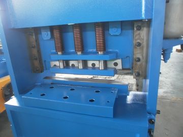
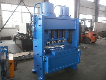
Product Details:
|
Highlight: | hydraulic guillotine shearing machine,sheet metal shearing machine |
---|
Specification:
No | Name | Value | Unit | Remarks | |
1 | Shearing Thickness | 20 | mm | ||
2 | Shearing Width | 600 | mm | ||
3 | Shearing Angle | 3° | |||
4 | Distance Between Vertical Columns | 1115 | mm | ||
5 | Blade Length | 700 | mm | ||
6 | Height of the Working Table | 800 | mm | ||
7 | Main Motor | Type | Y180L-4 | ||
Power | 22 | kw | |||
Speed | 1470 | r/min | |||
8 | Axial Plunger pump | Type | IGP5-H063 | ||
Power | 63 | L/min | |||
9 |
Dimension
|
L | 1400 | mm | |
W | 1500 | mm | |||
H | 2000 | mm |
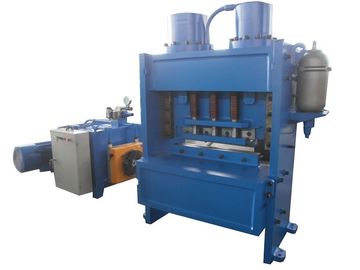
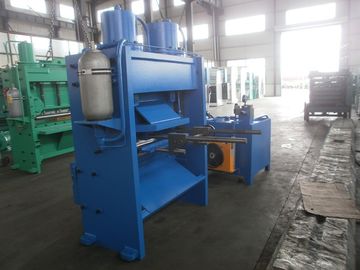
This machine is used for shearing of steel plates with thickness of 0.3-20mm and width of 600mm.
The strength of the plates to be shorn should be 450N/mm2,,If the plates of other strength are to be shorn, the thickness of them should be adjusted.
This machine is of welded steel structure, hydraulic driving. The return stroke is completed by accumulator .The machine is of good steadiness and safety while in use .And it does not occupy much space and is of low weight and good rigidity .The blade clearance can be adjusted quickly and simply . The stroke of upper blade beam can be adjusted freely, which improves the efficiency when cutting narrow plates. The machine is equipped with infrared sensor protection barrier to ensure safety.
Hydraulicc Driving System:
The hydraulic system(figure1)is made up of IGP5-H063 axial plunger pump 2,combined valve4.The whole system is reasonably arranged.
The needed pressure oil is produced by 40MCY14-1B axial plunger pump .The max system work pressure is 25Mpa .The return stroke of the upper blade beam is completed by accumulator, and the pressure is about 8Mpa.The working principle of hydraulic system (see figure 1)is: The oil generated by oil pump, through the pipes, enters each oil cylinder(main oil cylinder8,hold-down cylinder9)and combined valves4.After entering the combined valve, the oil is divided into main oil route and control oil route. The oil from control oil route, through the throttle hole, will enter magnetic directional valve which is on normal open position and go back to the oil tank. No pressure is formed in the main oil route. Because of the throttle hole, certain pressure difference is formed between its front and back, which opens conical valve, and the oil will go back to the return oil cylinder, through the oil return hole. No pressure is formed in the main oil route. And the machine will take no action. When the electromagnetic directional valve is switched on , the control oil will enter the relief valve through the magnetic directional valve. The overflow valve is closed under the set pressure, so the oil route pressure will increase gradually. And in this process, The upper bade beam will rest move down, only after the oil cylinder overcomes the supporting force for return. At this time the hold-down cylinder and upper blade beam are enabled to act in turn. The upper blade beam moves to the bottom dead point and will trigger the limit switch to act, the magnetic directional valve will reset after being powered off. The whole oil route is unloaded .the upper blade beam returns because of accumulator.
Contact Person: Mr. Wu
Tel: 0086 136 6511 7920
Fax: +86-510-68930088